 EN

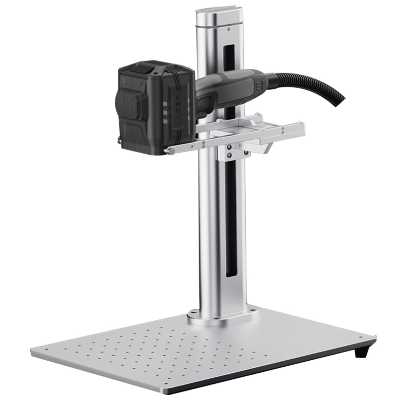
Why Laser Printers Excel for Permanent Electronic Component Marking
Direct Part Marking (DPM) Compliance with ISO/IEC 29158 for Traceability
Direct Part Marking (DPM) places machine-readable codes directly onto the component—eliminating reliance on labels that can peel, fade, or delaminate during soldering, thermal cycling, cleaning, or long-term service. ISO/IEC 29158:2018 defines the verification and grading criteria for DPM symbols—especially Data Matrix and QR codes—used across electronics manufacturing. Laser marking delivers high-contrast, high-modulation marks with sharp cell edges and no edge lift, ensuring reliable automated optical inspection (AOI) even after harsh environmental exposure. Because the mark is permanently fused into the substrate—not printed on top—it withstands heat, solvents, abrasion, and vibration without degradation. This durability supports unique serial numbers, date/batch codes, and regulatory compliance marks (CE, RoHS, WEEE), enabling full product traceability from wafer fab to field failure analysis.
Advantages Over Inkjet and Dot Peen: Non-contact, No Consumables, and Sub-20 µm Resolution
Inkjet marking introduces fluid handling risks—smearing, clogging, solvent incompatibility, and curing delays—while dot peen physically impacts fragile components, risking micro-cracks or leadframe deformation. Laser marking avoids both issues: it’s fully non-contact, eliminating mechanical stress and consumable dependency (no inks, ribbons, or labels). On ultra-miniature components—such as chip resistors, ceramic capacitors, or wafer-level packages—modern UV and fiber lasers achieve line widths under 20 µm, enabling readable codes on surfaces smaller than a grain of salt. The beam also accommodates curved, uneven, or transparent substrates without retooling. Unlike inkjet, there’s no risk of spreading or fading after exposure to flux removers or cleaning agents. The result is consistent, durable, machine-readable identification at production speeds—reducing downtime, setup changes, and consumable inventory.
Integrating Laser Printers into High-Speed Electronics Production Lines
A laser printer integrated into high-speed electronics production must function as a deterministic, synchronized node—not a standalone engraving station. Two core requirements ensure reliability: precise trigger synchronization with PLC/MES and stable code geometry at 40–60 parts per minute (ppm).
Synchronizing Laser Printer Triggers with PLC/MES for Real-Time Position Compensation
On fast-moving lines, relying solely on a part-in-place sensor creates positioning errors due to conveyor speed variation, mechanical vibration, and signal latency between detection and laser pulse. Robust integration requires the laser system to consume real-time encoder or resolver data—and cross-reference it with PLC and MES position commands via PROFINET, EtherNet/IP, or digital I/O handshakes. The MES supplies validated marking layouts and serialized code ranges; the PLC requests the next unique identifier without pausing the line. Real-time compensation adjusts galvanometer deflection or scan head position within 1–2 ms using measured offset values. At 0.5 m/s line speed, a 2 ms delay causes ~1 mm placement error; sub-millisecond response keeps deviation below 0.5 mm. Vision-assisted registration further corrects for rotation and translation—ensuring consistent code placement across irregular or flexible components.
Maintaining Code Consistency at 40–60 ppm: Adaptive Scan Lenses and Burst-Mode Pulse Control
At 40–60 ppm, each marking cycle allows less than one second—leaving minimal margin for thermal drift, focus shift, or reflectivity variation. Adaptive optics—including dynamic focusing units and precision F-theta lenses—maintain uniform spot size and depth of field across the entire marking field, ensuring edge-to-center code consistency. Burst-mode pulse control modulates laser energy at kilohertz rates, compensating in real time for thermal buildup and part-to-part surface differences (e.g., ceramic vs. metal leads). This preserves line width stability: a 20 µm variation can drop Data Matrix readability below ISO/IEC 29158 thresholds under standard verification lighting. Together, these features deliver repeatable, grade-compliant alphanumeric, QR, and 2D codes—without slowing throughput or compromising verification pass rates.
Material-Specific Laser Printer Configuration for Sensitive Electronics
UV (355 nm) vs. Fiber (1064 nm) Laser Printers: Matching Wavelength to Substrate (Ceramic, FR-4, Metal Leads)
Wavelength selection is foundational to effective, non-damaging marking. UV (355 nm) lasers use high-photon-energy cold ablation to mark ceramics and glass-reinforced FR-4 without carbonizing epoxy or damaging underlying copper layers. Fiber (1064 nm) lasers couple more efficiently into bare metals—producing clean, annealed marks on tin-, nickel-, or copper-plated leadframes. Ceramic substrates benefit from UV’s low heat-affected zone and fine contrast; FR-4 requires UV’s selective absorption by solder mask and epoxy to avoid glass-fiber exposure. While fiber lasers offer higher throughput on metal, they risk overheating thin dielectric films on PCBs or wafer-level packages. Use the table below to guide initial wavelength selection.
| Substrate | Recommended Laser | Reason |
|---|---|---|
| Ceramic | UV 355 nm | Low heat-affected zone, strong contrast |
| FR-4 PCB | UV 355 nm | Marks solder mask and epoxy with minimal carbonization |
| Metal leads | Fiber 1064 nm | Efficient coupling into copper, tin, or nickel finishes |
After selecting wavelength, optimize spot size and pulse duration to protect sensitive layers—particularly thin passivation or polymer films.
Preventing Thermal Damage: Pulse Energy Calibration for MLCCs, PCBs, and Wafer-Level Components
Pulse energy must be calibrated per component type and size to prevent latent damage. For multi-layer ceramic capacitors (MLCCs), keep pulse energy below 50 µJ to avoid microcracks in dielectric layers. On PCBs, combine short pulses with high scan speeds to prevent solder mask delamination or discoloration. Wafer-level components demand tight control over energy density—thin oxides and passivation layers can fracture under localized thermal stress. Always validate settings on sample pieces and inspect under 30–50× magnification before ramping up. Lower repetition rates and shorter pulse widths reduce cumulative heating. Burst-mode pulse control helps maintain legibility while limiting peak temperature rise. Document and store validated settings per part number—and revalidate when switching material lots or suppliers, as ceramic and polymer batches vary significantly in absorption and thermal response.
Optimizing Laser Printer Output for Industry 4.0 Traceability Requirements
In Industry 4.0, a laser printer’s output is not just a visible mark—it’s a structured data event embedded in the digital thread. To meet modern traceability standards, laser controllers must generate unique, serialized codes enriched with metadata: line ID, timestamp, material lot, operator ID, and equipment signature. Immediately post-marking, an inline vision system should grade the symbol against ISO/IEC 29158 parameters—including contrast, quiet zone, cell modulation, and grid distortion—and feed results back to the laser controller. If any parameter falls below threshold, the system must auto-divert or halt the part before downstream processing.
This closed-loop architecture extends to predictive maintenance. IoT sensors monitor pulse energy, scan velocity, galvo mirror position, and lens focus—comparing live values against baseline performance models. Predictive analytics flag subtle degradations before they cause unreadable codes, helping avoid unplanned downtime—an estimated $50 billion annual cost to industrial manufacturers (Deloitte, 2023). Recipe-driven operation centralizes control: MES-deployed recipes automatically configure wavelength, pulse duration, scan pattern, and serialization logic for each component. Serial number databases enforce uniqueness and validate identifiers pre-fire. With edge-based data aggregation, each laser printer becomes a traceability node—feeding real-time KPIs to dashboards, digital twins, and enterprise analytics platforms. That transforms marking from a passive step into a measurable, auditable, and self-optimizing link in the end-to-end manufacturing value chain.
FAQs on Laser Printers for Permanent Electronic Component Marking
Why are laser printers better than inkjet for electronic components?
Laser printers provide non-contact marking that eliminates mechanical stress and consumable dependency, ensuring durable and readable codes even under harsh environmental conditions.
What is the advantage of UV lasers over fiber lasers for sensitive substrates?
UV lasers use cold ablation to create marks on sensitive substrates like ceramic and FR-4 without causing thermal damage or carbonization, whereas fiber lasers are suited for metal surfaces due to their efficient coupling.
Can laser printers maintain traceability in Industry 4.0 factories?
Yes, laser printers in Industry 4.0 generate serialized codes enriched with metadata for traceability, integrate with MES systems, and provide predictive analytics to avoid downtime.
How do laser systems ensure placement accuracy during high-speed production?
Laser systems synchronize with PLC/MES and use real-time encoder data to adjust deflection or scan head positions, ensuring precise code placement even at high speeds.
Table of Contents
- Why Laser Printers Excel for Permanent Electronic Component Marking
- Integrating Laser Printers into High-Speed Electronics Production Lines
- Material-Specific Laser Printer Configuration for Sensitive Electronics
- Optimizing Laser Printer Output for Industry 4.0 Traceability Requirements
- FAQs on Laser Printers for Permanent Electronic Component Marking